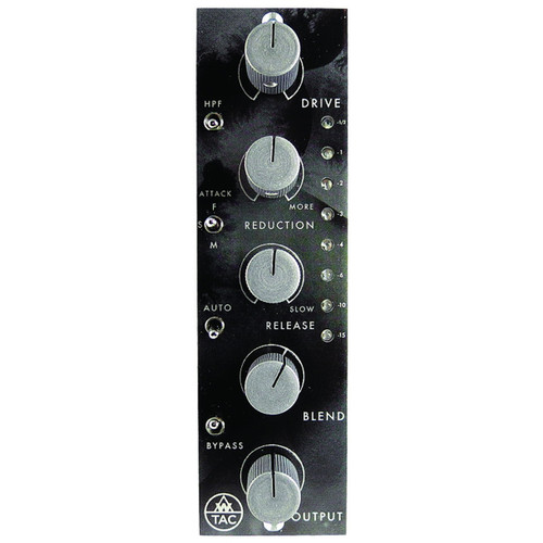
Front End Audio acquires previously owned gear through our Buy-Back program. You can purchase used gear at a great price but there are no manufacturer warranties with these items. These items have been inspected and/or tested by our staff to make sure each one is in working condition and comes with our commitment to service. This AwTAC Channel Compressor looks and functions perfectly. It doesn't include the original box but we will make sure it is packaged securely!
The AwTAC Channel Compressor 500-Series Compressor is a versatile, classic (if not elegant) sounding compressor with simple to use controls designed to stack well in a mix while providing everything from "just a little" to "suck all the air out of the room" amounts of compression. AwTAC's approach was to design an old sounding, not overly modern behaving compressor that can sound great on every channel of a console, build up well in a mix and be very quick and easy to get dialed in. The AwTAC Channel Compressor has a great subtle vibe which wont accidentally do too much, is never too grabby, and can easily be dialed in from fairly transparent operation to completely in your face. It does this effortlessly while maintaining a feels like it's London 1970 attitude.
- The AwTAC Channel Compressor is transformer balanced on its input and output for big iron sound and weight. Every single stage in both the audio and sidechain circuit is comprised of carefully tuned discrete transistor amplifiers.
- The AwTAC Channel Compressor features a 10k bridging input that will not load a converter feeding its input.
- The AwTAC Channel Compressor attenuates input signal after its input transformer, so it is possible to drive high level to the input for more transformer coloration if desired.
The sidechain uses a FET for its control element, which controls the gain of the input amplifier. The FET is in the sidechain only, the input amp is a bold sounding bipolar transistor amplifier which could work as the line level receiving amplifier in a console.The FET sidechain does not shunt signal from the input amp, but rather controls the gain of the input amp, so its easy to think of the sidechain as somewhat of an "auto-fader" if such a thing existed. What this makes for is a very very smooth sounding compression circuit that, while FET controlled, tends to feel a bit like an optical type compressor. The circuit maintains all the speed usually associated with FET compressors but has a very, very smooth quality commonly associated with optical compressors.
AwTAC Channel Compressor 500-Series Compressor Features
- Mono FET Compressor
- Single width 500 module
- 10 Channel Compressors fit in a Purple Audio Sweet Ten rack
- A Line Level Amplifier offers TRUE Parallel Compression (like doing it on a mixer - not just bleeding dry signal into the output)
- The entire AC audio path is through-hole, discrete construction
- The entire DC side chain is through-hole, discrete construction
- Features a soft knee compression characteristic - a "London 1970" attitude: Starts at 1:1 ratio once threshold is crossed and climbs to 10:1 where it stays. Varies from 1:1 to 20:1 according to signal level and threshold (soft knee). Nominally 10:1 when INPUT and REDUCTION controls set to their fully clockwise (maximum) positions.
- Feedback style compression circuit
- AwTAC Amplifiers are designed and tuned to sound Awesome when clipping
AwTAC Channel Compressor 500-Series Compressor Features
- Drive Pot sets the level to the FET Controlled Amp in the compressor circuit. Below unity, the Drive Pot will raise the level fed to the compressor. Above unity, the Drive Pot will raise the level of distortion in the compressor. Since the sidechain will not distort the FET controlled amp, the Drive Pot is there to add distortion when desired.
- HPF Switch engages a 6 dB/ Octave High Pass Filter to the side chain at 375 Hz. Seems like a high cut off point until you listen to it, the gradual slope allows your low end to breathe for a much more natural sounding vibe. Absolutely excellent on program material.
- Reduction Pot controls the amount of compression applied to your input signal. Turn clockwise for more compression, fully counterclockwise for Off.
- Attack Switch is a three position toggle switch which selects Fast (1.5 mS) in the up position, Medium (15 mS) in the down position and Slow (40 mS) in the middle position.
- Release Pot sets the release time from 75 mS to 3.4 Seconds. Fastest setting is full counterclockwise.
- Auto Switch engages an auto release circuit when the toggle is in the up position. When engaged, Release Pot orientation has no effect. The auto circuit is program dependent and very, very, smooth.
- Blend Pot is the fader for the Blend Amplifier which sets output level for the Parallel, uncompressed, circuit. Only the Parallel Blend signal is effected by this pot. Blend circuit provides +9dB of gain "in hand" similar to what is found on a proper console. Unity gain is denoted by the hash mark at 1 O'Clock. Full Counter Clockwise mutes the Parallel Blend signal.
- Output Pot is the fader for the Make-up Amp which sets the output level for the Compression Circuit. Only the compressed signal is effected by this Pot.
- Bypass Switch activates the relay controlled true bypass. In the up position, the compression and parallel blend circuits are engaged. In the down position the entire circuit AND transformers are bypassed at the edge connector: input signal comes in off the edge connector, through the relay and back out to the edge connector completely bypassing the Channel Compressor circuitry. When powered off, the unit defaults to "bypass" so signal will flow through with the rack off, no need to unpatch.
- Meter is an 8 segment peak detecting LED meter which displays gain reduction only in the following steps: -0.5 dB, -1 dB, -2 dB, -3dB, -4 dB, -6 dB, -10dB, -15dB The meter is always on, even with the unit in bypass.
AwTAC Channel Compressor 500-Series Compressor Specifications
- Input Voltage Range: +/-15 to 18VDC
- Power Consumption: +/-40mA
- Size: 5.24″ x 1.49″ x 6.06″
- Weight: >1lb
- Drive Control
- Unity gain (0 dB) at center (12 o'clock), with +7.8 dB fully clockwise and -9.6 dB fully counterclockwise, continuously variable
- High Pass Filter (HPF) Control
- Two-position toggle switch applies a first-order filter (6dB/octave) at approximately 375 Hz to the side chain signal when engaged (up)
- Reduction Control
- Level of signal sent to side chain, continuously variable from -infinity fully counterclockwise to unity gain fully clockwise
- Compression Characteristic
- Fixed attenuation followed by JFET-controlled variable amplification. Feedback design, peak-detecting, soft knee.
- Compression Threshold
- Varies according to position of DRIVE and REDUCTION controls. An incoming signal of approximately -24 dBu @ 1kHz is required for compression to begin (defined as -0.5 dB of gain reduction) when these controls are set to their fully clockwise (maximum) positions.
- Compression Ratio
- Varies from 1:1 to 20:1 according to signal level and threshold (soft knee). Nominally 10:1 when INPUT and REDUCTION controls set to their fully clockwise (maximum) positions.
- Attack Control
- Three-position toggle switch sets the side chain attack time
- 1.5mS (Fast) up
- 40mS (Slow) middle
- 15mS (Medium) down
- Three-position toggle switch sets the side chain attack time
- Release Control
- Release time continuously variable from 75mS fully counterclockwise to 3.4 Seconds fully clockwise
- Auto Control
- Two-position toggle switch defeats the release control and applies a program dependent release circuit when engaged (up)
- Blend Control
- Level of uncompressed signal continuously variable from -infinity fully counterclockwise to +9.3 dB fully clockwise, with unity gain (0 dB) at 1:30
- Output Control
- Level of compressed signal continuously variable from -infinity fully counterclockwise to +17.2 dB fully clockwise, with unity gain (0 dB) at 10:30
- Bypass Control
- Two-position toggle switch controls relay true bypass circuit, which selects between processed outgoing signal (up) and unprocessed incoming signal (down). Reverts to bypass (unprocessed) position when unit is powered off.
- Gain Reduction Metering
- Peak-detecting LED indication from -0.5 to -15 dB, in eight carefully selected steps. Displays real-time side chain voltage, regardless of bypass status.
- Line Input
- Nominally 10,000 Ω balanced bridging, transformer isolated
- +4 dBu operating level
- Line Output
- Nominally 90 Ω balanced, transformer isolated
- Max load 300 Ω or greater
- +4 dBu operating level
- Total Gain
- +27 dB if DRIVE and OUTPUT controls both set fully clockwise, with REDUCTION and BLEND both set fully counterclockwise
- Max Output for 1% THD+N @ 1kHz
- Nominally +18 dBu (depending power supply voltages)
- Max Input for 1% THD+N @ 1kHz
- Greater than +30 dBu (if controls turned counterclockwise, or gain reduction active, to sufficiently prevent max output condition)
- Noise (Compressed Output)
- RMS 22 Hz to 22khz Unweighted = -78 dBu
- RMS 400Hz to IEC-A Weighted = -79 dBu
- Selectively Filtered (dBu) = -85 max @ 20kHz to -114 min @ 20Hz, with -95 nominal in the mid band (circa 1kHz)
- Noise (Blend Output)
- RMS 22 Hz to 22khz Unweighted = -90 dBu
- RMS 400Hz to IEC-A Weighted = -93 dBu
- Selectively Filtered (dBu) = -96 max @ 20kHz to -122 min @ 20Hz, with -109 nominal in the mid band (circa 1kHz)
No review yet, Be first to Write a Review
Write a Review


 Sign Up for exclusive sales and offers!